|
Crank design
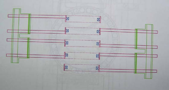
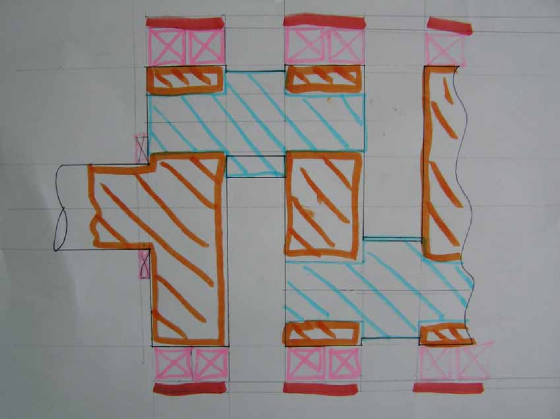
With this design there are two engine end plates one at the drive end and one at the non-drive end.
The engine head bolts run from the head to the bearing carrier, as one unit.
With this considered.
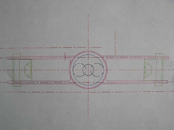
Oil feed
Oil is fed in from the non-drive end and this is pumped though from piston four to piston ones big end bearing-journal.
Main bearings are lubricated directly from the oil gallery in the crankcase.
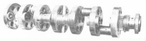
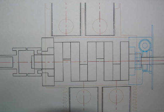
Construction
The unit is made of four big end journals
THese are pressed in to what would have been crankshaft webs, but I call crankshaft partitions for simplicity.
Each end has a power take of.
The PTO for the drive end drives a rubber coupling.
The PTO for the non drive end drives a helical gear 90 degree power take of for the sleeve drive, as well as a synchronies
belt drive for all auxiliary equipment.
Above is technical data on both models of the Tigers Maybach engine.
max RPM for bearing 4500 rpm
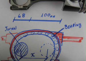
Main bearings
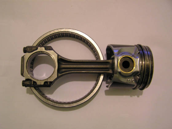
As you can see from the picture above, to get the maximum stroke length using the existing conrod, the thinner the bearing
the longer the stroke.
But one must also remember the loading on the bearing is quite high.
But there is about 30mm that the bearing can be wide.
Another option is to remove the inner bearing race from a roller or needle bearing and machine the crank shaft so that
the bearing runes directly on the crank shaft.
|